VLAN e collegamenti trunk
Topologia gerarchica con tre switch
Esercizio guidato — Cisco Packet Tracer 8.2.2
Teoria VLANGuida comandi switch
1. Topologia e consegna
In Cisco Packet Tracer 8.2.2 costruisci una rete con tre switch Cisco 2960 e dodici PC. Due switch di accesso collegano i PC; lo switch centrale raccoglie i collegamenti dei due switch di accesso. È una topologia gerarchica semplificata a due livelli, rappresentata orizzontalmente nello schema.
Crea le VLAN 10, 20 e 30 su tutti gli switch. Le porte verso i PC devono essere access; i collegamenti tra switch devono essere trunk e trasportare tutte e tre le VLAN.
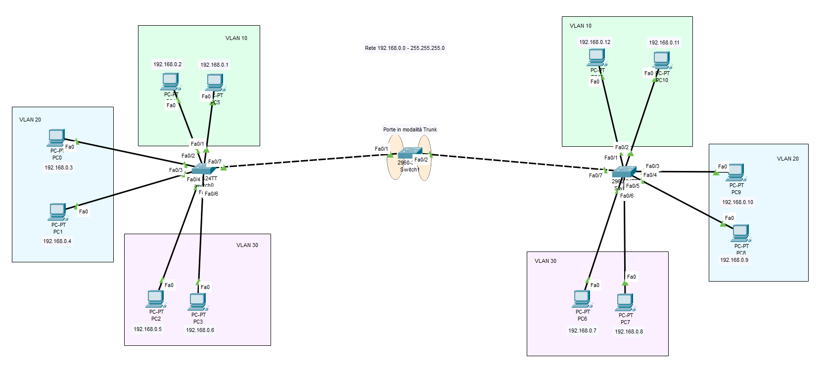
- Sinistro
Fa0/7↔ centraleFa0/1. - Centrale
Fa0/2↔ destroFa0/7. - PC collegati alle porte
Fa0/1–Fa0/6dei due switch di accesso.
Usa Copper Straight-Through per PC–switch e Copper Cross-Over per switch–switch. Attendi la transizione iniziale di Spanning Tree prima dei test.
Il trunk estende ciascuna VLAN sui diversi switch: non unisce VLAN differenti e non realizza routing tra VLAN.
2. Indirizzi dei PC
Apri Desktop → IP Configuration → Static. Imposta la maschera 255.255.255.0 su tutti i PC; lascia gateway e DNS vuoti. Controlla le etichette delle porte sul cavo prima di assegnare gli indirizzi.
| Switch | Porta access | IP del PC | VLAN |
|---|---|---|---|
| Sinistro | Fa0/1 | 192.168.0.1 | 10 |
| Sinistro | Fa0/2 | 192.168.0.2 | 10 |
| Sinistro | Fa0/3 | 192.168.0.3 | 20 |
| Sinistro | Fa0/4 | 192.168.0.4 | 20 |
| Sinistro | Fa0/5 | 192.168.0.5 | 30 |
| Sinistro | Fa0/6 | 192.168.0.6 | 30 |
| Destro | Fa0/1 | 192.168.0.11 | 10 |
| Destro | Fa0/2 | 192.168.0.12 | 10 |
| Destro | Fa0/3 | 192.168.0.10 | 20 |
| Destro | Fa0/4 | 192.168.0.9 | 20 |
| Destro | Fa0/5 | 192.168.0.7 | 30 |
| Destro | Fa0/6 | 192.168.0.8 | 30 |
3. Switch sinistro: VLAN e porte access
Apri la CLI. Se compare la domanda sulla configurazione iniziale, rispondi no. Dal prompt Switch> esegui:
enable
configure terminal

vlan 10
exit
vlan 20
exit
vlan 30
exit

interface fastEthernet 0/1
 switchport mode access
 switchport access vlan 10
exit

interface fastEthernet 0/2
 switchport mode access
 switchport access vlan 10
exit

interface fastEthernet 0/3
 switchport mode access
 switchport access vlan 20
exit

interface fastEthernet 0/4
 switchport mode access
 switchport access vlan 20
exit

interface fastEthernet 0/5
 switchport mode access
 switchport access vlan 30
exit

interface fastEthernet 0/6
 switchport mode access
 switchport access vlan 30
exit

end
show vlan brief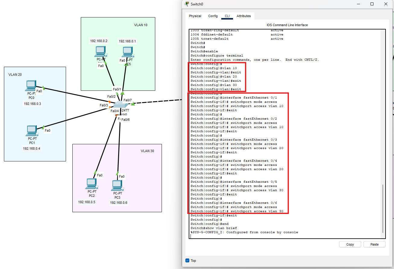
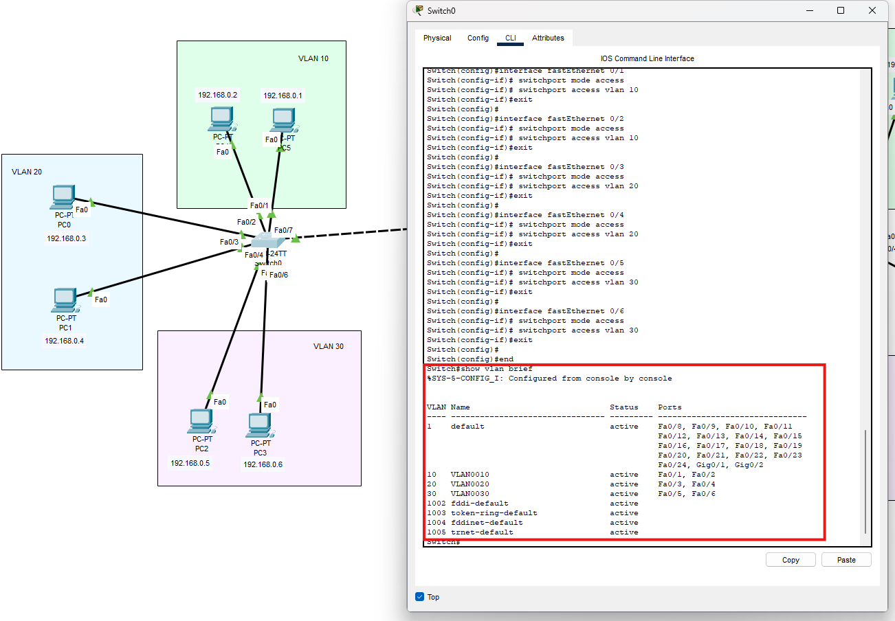
4. Switch destro: VLAN, access e trunk
Le VLAN e le porte access seguono gli stessi gruppi del sinistro. Anche qui Fa0/7 collega lo switch al centrale.
enable
configure terminal

vlan 10
exit
vlan 20
exit
vlan 30
exit

interface fastEthernet 0/1
 switchport mode access
 switchport access vlan 10
exit

interface fastEthernet 0/2
 switchport mode access
 switchport access vlan 10
exit

interface fastEthernet 0/3
 switchport mode access
 switchport access vlan 20
exit

interface fastEthernet 0/4
 switchport mode access
 switchport access vlan 20
exit

interface fastEthernet 0/5
 switchport mode access
 switchport access vlan 30
exit

interface fastEthernet 0/6
 switchport mode access
 switchport access vlan 30
exit

interface fastEthernet 0/7
 switchport mode trunk
 switchport trunk allowed vlan 10,20,30
exit

end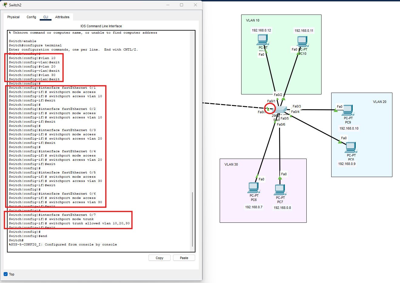
5. Switch sinistro: trunk verso il centrale
Dal prompt Switch#:
configure terminal

interface fastEthernet 0/7
 switchport mode trunk
 switchport trunk allowed vlan 10,20,30
exit

end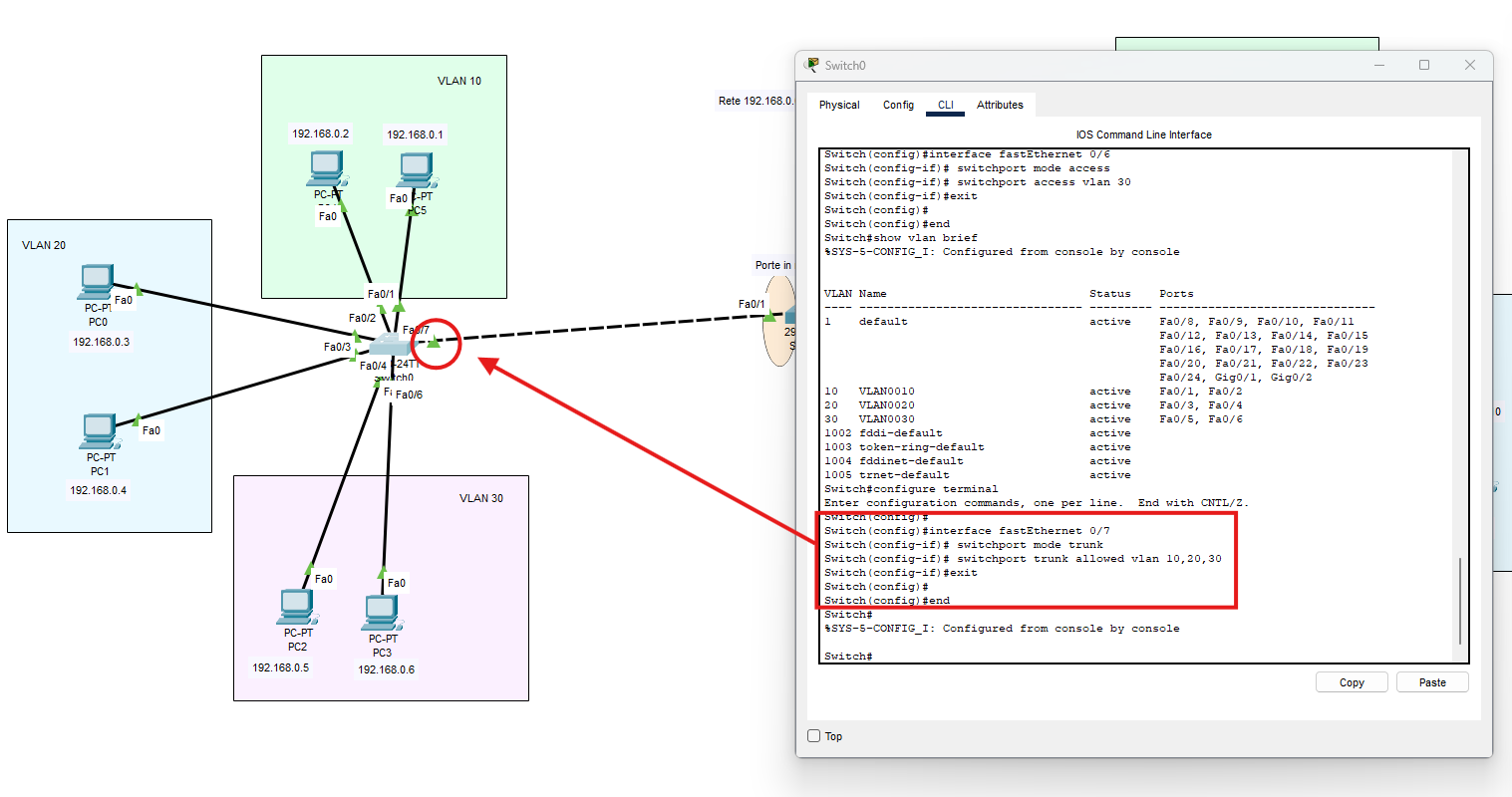
6. Switch centrale: VLAN e due trunk
Crea le VLAN anche sul centrale, benché non abbia PC collegati. Un trunk non crea automaticamente le VLAN che deve trasportare.
enable
configure terminal

vlan 10
exit
vlan 20
exit
vlan 30
exit

interface fastEthernet 0/1
 switchport mode trunk
 switchport trunk allowed vlan 10,20,30
exit

interface fastEthernet 0/2
 switchport mode trunk
 switchport trunk allowed vlan 10,20,30
exit

end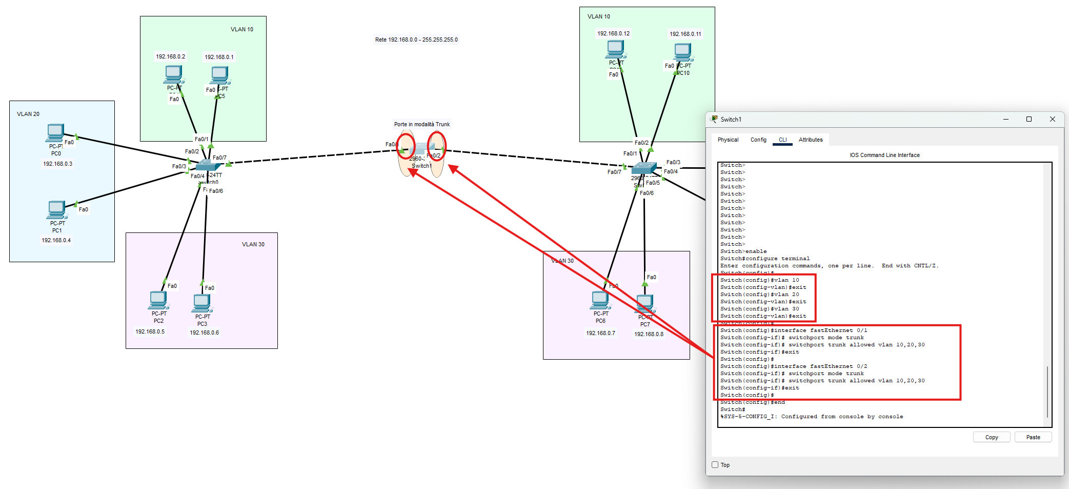
7. Verificare la configurazione
Esegui su ciascuno switch dal prompt Switch#:
show vlan brief
show interfaces trunk
show mac address-table- Trunk attesi: sinistro Fa0/7; centrale Fa0/1 e Fa0/2; destro Fa0/7.
- In
show interfaces trunk: statotrunking; VLAN 10,20,30 consentite, attive e in forwarding. - La native VLAN resta quella predefinita, VLAN 1, uguale alle due estremità. La lista allowed trasporta il traffico delle VLAN 10,20,30.
- Le porte trunk normalmente non compaiono tra le porte access di
show vlan brief: controllale conshow interfaces trunk.
La tabella MAC si popola quando gli host generano traffico. Lo switch apprende il MAC sorgente e lo associa alla VLAN e alla porta di ingresso.
8. Prove da svolgere in classe
Esegui le prove in classe e confronta il risultato osservato con quello atteso. Dal PC sorgente apri Desktop → Command Prompt.
| Sorgente | Comando | Risultato atteso | Motivo |
|---|---|---|---|
| 192.168.0.1 | ping 192.168.0.2 | Riesce | VLAN 10, stesso switch |
| 192.168.0.1 | ping 192.168.0.11 | Riesce | VLAN 10 attraverso entrambi i trunk |
| 192.168.0.1 | ping 192.168.0.9 | Fallisce | VLAN 10 verso VLAN 20, senza routing |
| 192.168.0.3 | ping 192.168.0.9 | Riesce | VLAN 20 attraverso entrambi i trunk |
| 192.168.0.5 | ping 192.168.0.7 | Riesce | VLAN 30 attraverso entrambi i trunk |
Attendi che le porte siano operative; se la prima richiesta fallisce durante la risoluzione ARP, ripeti il ping. Per comunicare nella stessa VLAN su switch diversi non serve un router.
Osservazione in Simulation
- In Edit Filters seleziona ARP e ICMP.
- Esegui un ping tra PC della stessa VLAN su switch diversi.
- Avanza con Capture/Forward e apri i dettagli degli eventi.
- Se manca l’associazione nella cache, osserva la richiesta ARP broadcast: attraversa i trunk nella VLAN di origine, senza raggiungere i PC delle altre VLAN.
- Controlla
show mac address-tablesul centrale: i MAC dei PC vengono appresi sulle porte trunk. Sul PC usaarp -a.
9. Se un ping nella stessa VLAN continua a fallire
- Controlla IP univoci, maschera /24 e porte effettivamente cablate.
- Verifica modalità access e VLAN delle porte dei PC.
- Verifica la presenza delle tre VLAN su tutti gli switch.
- Controlla che i trunk siano operativi ai due estremi e che la VLAN sia consentita, attiva e in forwarding lungo tutto il percorso.
Per esaminare una porta, ad esempio Fa0/1:
show interfaces fastEthernet 0/1 switchport
show interfaces fastEthernet 0/1
10. Salvare e consegnare
Su ciascuno switch:
copy running-config startup-configAlla richiesta Destination filename [startup-config]? premi Invio. Salva anche il progetto con File → Save As in formato .pkt.
Consegna il progetto e una tabella con sorgente, destinazione, VLAN, risultato atteso e risultato osservato per i cinque ping. Spiega perché un collegamento trunk consente di estendere una VLAN ma non permette di comunicare tra VLAN diverse.